Okay, now we will master methods of disassembly and assembly works at replacement of the damaged cylinder head. In addition, you learn how to repair cylinder head DIY.
Firstly, you need to remove the defective cylinder head. So we will talking about how to remove an engine head from engine block. And you should know what the details and tools you can to use for it.
Before starting the dismantling work of engine head, the cooling liquid must be drained from the engine cooling system through special taps of the expansion tank.

It is recommended to use pneumatic and electric wrenches in the process of disassembly and assembly work.
These assembly units are necessary for reuse after dismantling (subject to their suitability), so don`t throw them far.
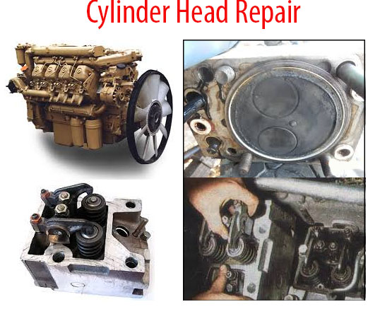
1. Exhaust manifolds; 2 – fine fuel filter; 3 – air brake compressor; 4 – intake manifold; 5 – rocker arms; 6 – pusher rods; 7 – cylinder head bolts; 8 – cylinder head covers; 9 – nozzles; 10 – injector mounting brackets.
All units and parts must be thoroughly cleaned, washed. After this you need to defect the details. All parts with defects must be replaced with new ones or restored. All gaskets also must be replaced with new gaskets.
All bolts, nuts, washers removed during disassembly are sorted by type and size. Bolts and nuts with worn or wrinkled faces are not allowed to be assembled.
Assembly units and parts which use to install the cylinder head:
- new cylinder head with valves assembly or remanufactured;
- cylinder head gasket;
- gasket cylinder head seal;
- cylinder head cover gasket;
- gasket for water pipe flange;
- ring sealing;
- sealing washer;
- intake manifold gasket;
- compressor housing gasket;
- branch pipe gasket;
- gasket;

After head cylinder assembly work you need adjust the gaps between the valves and rocker arms, then fill the engine with fresh engine oil, coolant, and then start the engine. The engine should work without interruptions, knocks and extraneous noise.
Wait to engine warming up and check the tightness of the joints. There should be no trace of coolant, engine oil or fuel in the connections. Gas breakthrough through gaskets is not allowed too.
Equipment and tools for removing the block head:
- Stand for mounting the engine;
- Bench with a bench vise;
- Measuring ruler with a change limit of 300 mm;
- Caliper;
- Feeler;
- Torque wrench with a maximum torque;
- Screwdriver;
- Socket Set;
- Pliers;
- Puller of nozzle;

Map of Cylinder Head Repair
Remove the three bolts securing the exhaust right manifold. Then remove the manifold assembly and four gaskets. Put the collector on a workbench. Do the same operations for the left exhaust manifold.
Unscrew union nuts of: water supply pipes to the compressor, connecting pipe from the compressor to the expansion tank and pipes from the compressor to the pressure regulator.

Release the compressor from the pipes. Remove the four mounting bolts of compressor. Remove the compressor together with the compressor housing gasket, and put the compressor on a workbench.
Remove the three bolts of fuel lines, and release the pipelines. Unscrew the two nuts of the fuel fine filter. Remove the filter, put it on a workbench. Remove the four bolts of the intake manifold connecting pipe. Remove the connecting pipe with gaskets.
Unscrew the union nuts on the fittings of the power steering pump of the pump low pressure pipe of the high pressure pipe of the pump. Release the power steering pump low and high pressure pipes from the power steering system piping. Unscrew the bolts of the pipe clamp.
Unscrew bolts for supplying fuel pipelines to injection pump. Release the pipelines, put the bolts with copper washers in place, tighten two or three turns.
Remove eight bolts securing intake manifold. Remove the right intake manifold. Remove assembly with the distribution tank of the cooling system and pipes, as well as fuel pipelines attached to it. Remove the four inlet manifold gaskets. Remove the left intake manifold too.
Release eight bolts of the water right pipe, remove the flat and spring washers. Repeat the same for the left pipe.
Unscrew the four nuts of nozzles on the cylinder heads of the right row. Remove the injector mounting brackets, remove the injectors together with the O-rings and washers. Put the nozzles on a workbench. Do these works for the nozzles on the cylinder heads of the left row.

Release four bolts securing cylinder head covers in right row. Remove the cylinder head covers. Remove the cover gaskets.
Release four bolts securing cylinder head covers in right row. Remove the cylinder head covers and the cover gaskets. Repeat the same acts for the left cylinder head covers. Loosen the two rocker arm mounting nuts on the head of the first cylinder. Remove the strut arm assembly with the rocker arms, two pusher rods assembly. Repeat the same for the heads of the second to eighth cylinders. Loosen the four bolts securing the head of the first cylinder, following the same sequence as when tightening.
Release the screws and remove washers. Then remove the cylinder head with valves. Remove the rubber gasket and cylinder head gasket. Remove the gasket of the water pipe flange. Repeat to remove the heads of the second to eighth cylinders.
Parts for installing cylinder heads on the engine
- cylinder head with valves assembly;
- gasket for water pipe flange – 8 pcs;
- cylinder head gasket – 8 pcs;
- gasket cylinder head seal – 8 pcs;
- rack of the rocker arm assembly with rocker arms;
- pusher rod assembly – 16 pcs;
- cylinder head bolt – 32 pcs;
- cylinder head cover – 8 pcs;
- cylinder head cover gasket – 8 pcs;
- nozzle assembly -8 pcs;
- nozzle mounting bracket – 16 pcs;
- sealing washer – 8 pcs;
- O-ring – 8 pcs.

Install the head gasket on the collar of the cylinder liner; install the cylinder head gasket;install the cylinder head assembly with valves. Wrap four bolts of the head fastening, having previously put on each washer and having greased the thread with graphite lubricant. Tighten the bolts according to the diagram with a torque wrench in three steps to 40-50 N * m, 120-150 Nm, 160-180 Nm, for uncoated bolts 190-210 N * m.
Install the rocker arm assembly on the studs and pins of the first cylinder head, having previously installed the pusher rods assembly. Install the stand fastening lock washer, tighten the two nuts, tighten them with a torque wrench to 42-54 N * m, lock the nuts with the washer. Repeat to install the rocker arm assembly with the rocker arms for the heads of the second to eighth cylinders.
Adjust clearances between valves and rocker arms. Install the cylinder head cover gasket and head cover.
Install the nozzle assembly into the head of the first cylinder with a sealing washer and a sealing ring , having previously turned out the housing plug; Install the nozzle mounting brackets and screw on the nut; tighten to 32-40N * m.
Install a water pipe flange gasket between the head of the first cylinder and the watermark flange and unscrew the two bolts, putting on the spring and flat washers
Repeat the same for the heads of the second to eighth cylinders. Tighten finally the pipe mounting bolts with water right and left to 30-53 N * m.
Use set of new and workable parts for installing intake manifolds left and right.
Install four gaskets of the inlet left manifold on the left row of heads, the inlet left manifold assembly , screw in the eight manifold mounting bolts with the wavy washers on them, tighten the bolts with a torque wrench to 50-62 N * m.
Install four gaskets of the intake right manifold , the right intake manifold assembly, pipes and fuel pipelines on the right row of heads. mounted on it (return the eight collector mounting bolts with the wavy washers on them. Tighten the bolts with a torque wrench to a torque of 50-62 N * m. Connect the free end of the overflow pipe of the expansion tank with the water outlet from the expansion tank to water pump. Tighten the clamp.
Connect the free end of the radiator vent pipe to the
expansion tank. Tighten the clamp. Screw the union nut of the bypass pipe from
the engine to the expansion tank onto the inlet of the left intake manifold.
Tighten the union nuts on the inlet left manifold and expansion tank.
Remove the bolts for connecting the fuel pipelines to the high-pressure fuel pump; connect them to the pipelines with copper washers, unscrew the bolts, tighten with a torque wrench to 40-50 N * m.
Release screws for fastening low and high pressure pipes of power steering pump to inlet left manifold and to left water pipe. Install the high pressure pipe of the pump and the low pressure pipe of the pump screw the union nuts of the pipes of the power steering system. Install the pipe clamps to the left inlet manifold and left water pipe. Screw in the bolts, tighten with a torque wrench to a torque of 15-20 N * m.
To provide a complete set of new and efficient parts for installing the connecting pipe of the intake manifolds and the air brake compressor:
- – connecting pipe for intake manifolds assembly – 1 pc;
- – gasket of the connecting pipe – 2 pcs;
- – fuel fine filter – 1 pc;
- – pneumatic brake compressor assembly) – 1 pc;
- – Compressor housing gasket – 1 pc.
Install the intake manifold connecting pipe together with the gaskets. Screw in the four mounting bolts, putting on the wavy washers on them, tighten with a torque wrench to a torque of 50-62 N * m.
Install the fuel fine filter on the studs of the intake manifold connecting pipe, put on two flat and spring washers, tighten the nuts, tighten all the way. Release the bolts connecting the fuel pipelines to the filter, connect them to the fuel pipelines by installing copper washers, tighten the bolts, tighten with a torque wrench to 40-50 N * m.
Remove the transport plug of the compressor gear (5320-3909137). Install the air brake compressor assembly with gasket, providing a seal on the compressor suction pipe.
Screw in four fastening bots, wearing spring washers. Tighten
the bolts to 50-52 N * m. Screw the union nut of the water supply pipe to the
compressor the union nut of the connecting pipe from the compressor to
Expansion tank union nut of the tube from the compressor to the pressure
regulator. Tighten the flare nuts at both ends of the tubes. Fasten the tube
from the compressor to the pressure regulator on the bracket.
Remove the bolts of the fuel drainage tube from the nozzles
of the left row of 7 cylinder heads, install the fuel drainage pipes, connecting
it with the bolts, installing the copper washers, screw the screws, tighten.
Repeat the same for the fuel drain pipe of the nozzles of the right row of
heads. Remove the plastic plugs from the nozzle connections. Screw the fuel
pipe overhead nuts on the nozzle fittings on the left-hand side of the cylinder
heads. Tighten the nuts at both ends of each tube. Secure the fuel pipes with
two mounting brackets.Tighten the two bolts.
Repeat the same for the fuel pipes of the right row of
cylinder heads. Install the intake manifold of the right row of cylinders assembly
with the exhaust manifold nozzles together with the four nozzle gaskets. Screw
in the three bolts securing the exhaust manifold to the block and screw on
eight nuts securing the exhaust manifold nozzles to the heads of the block,
putting on the disk washers. Tighten with a torque wrench to a torque of 50-62
N m.