
An ignition coil or a spark coil is an induction coil in car’s ignition system. It transforms the battery’s low voltage to the high voltage current needed to ignite the fuel.
The low voltage current converts to high voltage current in the ignition coil. The ignition coil construction may differ in the number of turns, the diameter of the leads of the primary and secondary windings and the corresponding connection between the windings.
Ignition Coil Construction
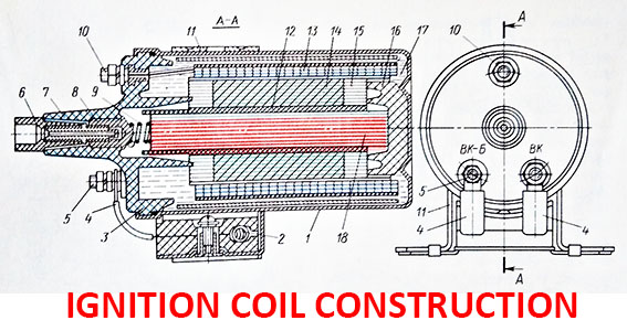
1 – housing; 2 – resistor; 3 – resistor holder; 4 – tire; 5 – high voltage clamp; 6 – high voltage output; 7 – cover; 8 – secondary contact; 9 – spring; 10 – low voltage clamp; 11 – ignition coil mounting bracket; 12 – current conductor; 13 – primary winding; 14 – secondary winding; 15 – insulating gaskets; 16 – insulator; 17 – oil; 18 – magnetic core; 19 – output.
An ignition coil has magnetic circuit 18 which consists of separate strips of electrical steel isolated between each other by a scale. An insulating tube of electrical cardboard is put on top of the magnetic circuit, on which the secondary winding 14 is wound first, and then the primary winding 13. With this arrangement of the windings, the heating of the ignition coil during engine operation is reduced.
One end of the secondary winding 14 is connected to the primary winding 13, and the other to the output terminal 8. With such a connection of the windings between them there is an electric or magnetic connection. The ends of the primary winding are connected to the clamps 5 and 10. A layer of insulating paper and an annular magnetic core made of transformer iron are located on top of the primary winding to enhance magnetic flux and remove heat.
The magnetic core with windings is placed in a sealed enclosure 1 and secured in it by an insulator 16 and a cover 7. The space between the casing and the windings is filled with transformer oil, which improves insulation and removes heat from the windings. During the operation of the interrupter, the current in the primary winding of the ignition coil is constantly changing: it decreases when the contacts open and increases when they are closed. The current strength in the primary winding depends on the duration of the circuit breaker contacts.
In the case of a higher rotational speed of the crankshaft, the contacts close for a very short time: in this case, the current strength in the primary winding and the voltage on the secondary are reduced.
The operation of a multi-cylinder engine under these conditions becomes unstable as a result of interruptions in the contact system of the battery ignition. For reduce these negative phenomena, a resistor 2 is included in the primary winding. This leads to the fact that the resistance of the primary winding of the ignition coil becomes variable: at a low speed of rotation of the crankshaft, it increases, at a high frequency, it decreases, and the current increases somewhat.
During the period of starting the engine with a starter that consumes a large current, the voltage at the pole terminals of the battery decreases and the current in the primary winding of the ignition coil decreases. Therefore, the resistor at the time of starting the motor is bridged by the contacts of the starter.