The steering gear includes a system of rods, hinges and levers, with the steering mechanism turning the steering wheels. The steering gear has a steering trapezoid, which allows you to rotate the steered wheels at different angles, thereby achieving their rolling without side slippage. The steering trapezoid can be rear or front, i.e., with a transverse steering link located behind or in front of the front axle. A distinction is made between a solid (single) trapezoid used for dependent suspension of wheels and dissected, used with independent suspension.
Car steering
The steering drive of trucks with dependent suspension includes: a bipod, a longitudinal link, two left pivot arms, a transverse link, a right pivot arm, a steering trapezoid (an articulated quadrangle formed by the middle part of the front axle beam, a transverse link and left and right pivot arms).
When the car is moving on rough roads, the steering gear parts (bipod, longitudinal and transverse steering rods, steering levers) are subject to heavy loads. Therefore, springs are introduced into the steering drive to mitigate the shocks and to automatically eliminate the gaps that occur when parts are worn. The tie rod at one end has a left-hand thread and a right-hand thread at the other for screwing on the ball joint mounting tips. As a result of this, the distance between the joints can be changed when adjusting the toe-in of the steered wheels.
Independent Suspension Steering
With an independent suspension of the steered wheels of cars, the steering gear includes (with a worm steering mechanism): a bipod; pendulum arm; a composite transverse link consisting of a middle link pivotally connected at the ends with a bipod and a pendulum arm and two lateral links; left and right swing levers.
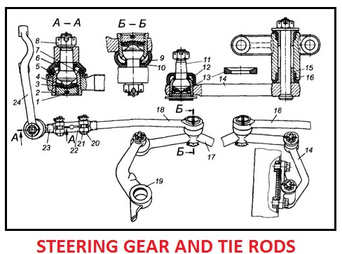
Steering drive and tie rods of a car

1 – cotter pin; 2 – threaded plug; 3 – spring; 4 – supporting heel; 5 – hinge body; 6 and 10 – rubber seals; 7 — tip spacer; 8 – a nut; 9 — thrust spacer; 11 – a spherical finger; 12 – hinge body; 13 – polyethylene cracker; 14 – pendulum lever; 15 – sleeve made of powder material; 16 – rubber sleeve of the lever; 17 – transverse thrust; 18 – lateral draft; 19 – bipod; 20 – a bolt; 21 – a coupling collar; 22 – an adjusting tube; 23 – thrust tip; 24 – the lever of the steering knuckle.
The independent suspension of passenger cars with rack and
pinion steering gear consists of a composite transverse link, the middle part
of which is the gear rack of the steering mechanism, and the side links are
pivotally attached to it (at the ends or in one place). The side rods, in turn,
are pivotally attached to the pivoting levers (left and right). The trapezoid
consists of the middle part of the front axle, the composite transverse link
and the pivoting (left and right) levers.
Hinges of steering drives. The main requirements for steering joints are without gaps and wear resistance. Therefore, all hinges are tightened by the sliding surface by deformation of the elastic element. In the articulation of the ball pin with the longitudinal steering link, one of the crackers (insert) is a rigid support, and the other is supported by a spring. The external cracker is pressed against the ball joint by a threaded plug. In all joints, crackers are constantly pressed against the head of a ball finger under the action of springs. Hinge rods with hemispherical fingers self-adjusting collapsible. The use of high-quality structural materials for crackers, modern lubricants and reliable seals allows the use of hinges that do not require replacement of the lubricant throughout their entire life.
Swivel steering gear parts:

1 – oiler; 2 – heels; 3 – conical spring; 4 – cover; 5-snap ring; 6 and 15 – tips; 7 and 17 — pipes; 8 – rubber ring; 9 – clip; 10 – rubber cap; 11 – ring; 12 – hemispherical finger; 13 and 19 – crackers; 14-shift liner; 16 – a collar; 18 – cork; 20 – spring; 21 – limiter.