
Braking Systems are provide reducing the speed of a car and fully stop it, when need. Also brakes are use in case when we need to keep the car on the place. The brake system must to be most efficiency during the braking under different driving loads.
Types of Braking Systems
- Service brake system — is used during the riding of the car to reduce the speed and full stop;
- Parking Brake system — is used to keep the stopped car on the place;
- Spare Brake system`s purpose is — stop the car when service brake system failure;
- Auxiliary Brake system is using like as brake-retarder on the Trucks during a long braking (for example: by the long downhill).
- Trailer brake system – is used to reduce trailers` speed, and also automatically braking in the event of a breakage in the coupling with the truck.
Car Brake System Diagram
Braking system consists of drives and brake mechanisms which provide braking of rotating wheels or one of the transmission`s shaft. Determination of car brake system efficiency is doing by the method of braking distance estimate (from press pedal moment to fully stop the car). Most efficiency braking result can be reached with use front and rear wheels braking at one time.
If you want to understand braking system more detail read the information how a disk brake work and how a drum brake work.
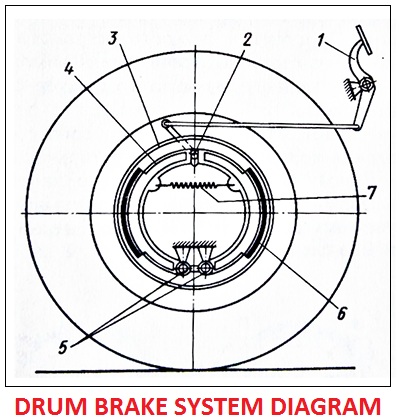
Drum brake system diagram
Drum Brakes Construction: 1 – pedal; 2 – expanding brake cam; 3 – brake drum; 4 – brake shoe; 5 – brake shoe pins; 6 – brake shoe plate; 7 – brake shoe return spring.
What are the differents between Drum brakes and Disk Brakes?
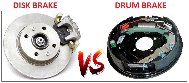
In drum brakes system, friction forces are generated on the inner surface of the brake cylinder, but in disk brakes friction forces are generated on the side surfaces of the rotating disk.
Wheel brake mechanism has pair brake shoes 4, which mounted inside the brake drum 3. Brake drum is rotating with wheel hub. Brake shoes are mounted on unmoving brake disk, based on the brake shoe pins 5, and pulled together by a spring 7.
On the surface of the brakes shoes facing to the brake drum, friction linings 6 are installed. When press the pedal 1, the brake cams 2 move the brake shoes to touch brake drum 3. The friction between brake drum and brake shoes do the wheel braking. When the brake pedal released, the spring 7 returns the brake shoes on their place.