Generator Construction
The generator converts mechanical energy into electrical energy needed to power all the electrical equipment of the car (except the starter) and to charge the battery. It is the main source of electricity for a car. There are two types of generator: alternator or direct current generator.

We have to know how to alternator works, because it has simpler construction and it`s more popular than direct current generator on the modern car.
Alternator is a three-phase twelve-pole synchronous electrical machine with a block of semiconductor rectifiers – silicon diodes that convert alternating current to constant current. The generator rotor is driven from the engine crankshaft pulley using a belt drive.
The generator consists of a stator, a rotor, two covers 2 and 13, a fan 7 and a pulley 10. The stator magnetic circuit is made up of individual insulated steel plates. On the inner side of the stator there are 18 lugs on which coils are mounted. They are divided into three groups of six successively connected coils connected according to a star scheme.
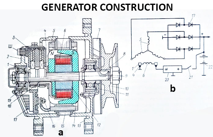
Generator Construction Scheme

a – alternator construction; b – electrical circuit; 1 – slip rings; 2 and 13 – end shields; 3 – generator brush holder; 4 – generator brush; 5 – stator winding; 6 – field winding; 7 – fan; 8 – spline; 9 – generator shaft; 10 – pulley; 11 and 19 – hermetic bearing; 12 – bush; 14 – pole pieces; 15 – stator magnetic circuit; 16 – output diodes; 17 – rectifier silicon diode unit; 18 – insulating bushings; 20 – voltage regulator; 21 – ignition switch; 22 – accumulator; Ш – output insulated from the housing.
The other ends of the phases with leads 16 are connected to the block of silicon diodes of the rectifier 17. In this case, each phase is connected with two diodes of different polarity. On the shaft of the generator 9 pressed sleeve 12, pole pieces 14 and insulating sleeve 18 slip rings 1. There is located the excitation winding 6 between the pole tips on the sleeve. The ends of the winding 6 are soldered to the contact rings to which the brushes 4 on the brush holder 3 are pressed.
One brush is connected to the generator housing, and the second is isolated from it and connected to the output terminal C. The pole tips have six poles of different polarity (N and S), forming a twelve-pole magnetic system. When the rotor rotates, the magnet lines of force cross the stator winding, energizing electromotive force in it, which is variable by magnitude and direction.
The excitation winding of the generator 6 when starting the engine receives power from the battery, and during operation of the engine from the rectifier.
The generator has three outputs: positive – to connect to the battery and the load; pin Ш for connection with pin Ш of voltage regulator; negative output – for connection to the vehicle weight and the voltage regulator.