Gear-shift Mechanism Construction
The Gear-shift Mechanism which shifts gears is usually located in the gearbox cover and is driven by a rocker lever. For example, in the gearbox Gear-shift mechanism of a truck, the lever 51 mounted directly on the gearbox swings freely in the spherical socket of the gearbox cover, resting on it with a ball-shaped bulge. The lever is held by a spring and a clamp 50. The lower end of the lever 51 enters in the groove of one of the forks mounted on the sliders 54 and 55.
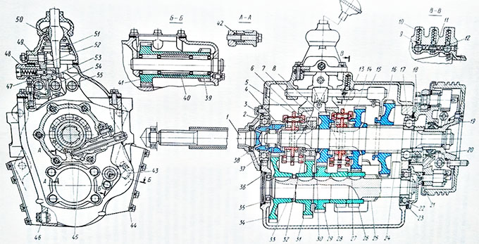
Five-speed gearbox construction: 1 – drive shaft; 2, 17,22,35,37 and 39 – bearing; 3,21,23,36 – locking rings; 4 and 34 – permanent gearing gears of drive and intermediate shafts; 5 – synchronizer 4th and 5th gears; 6 – fourth gear bushing; 7 and 31 – gear wheels of 4th gear; 8 and 29 – gear wheels of 3rd gear; 9 – ball of clamp; 10 – clamp spring; 11 – gearshift lock pin; 12- ball of the lock; 13 – synchronizer 2nd and 4th gears; 14, 26 – gear wheels of 2nd gear; 15 – first gear shift and reverse gear fork; 16 – gear wheel of the first gear and reverse gear; 18 – parking brake bracket; 19 – universal joint flange; 2 and 38 – oil seals; 24 – driven shaft; 25 – drive gear wheel of the first gear; 27, 30 and 32 thrust washers; 28 – gear wheel reverse of intermediate shaft; 33 – intermediate shaft; 40 – spacer sleeve; 41 – gear wheels block of reverse; 42 – mounting sleeve; 43 – control plug; 44 – cap sunroof; 45 – speedometer drive gear; 46 – drain plug with a magnet; 47 – breather; 48 – first and reverse gear fuse; 49 – axis of intermediate lever; 50 – retainer; 51 – gear shift lever; 52 – intermediate lever; 53 –slider first gear shift and reverse gear; 54 – slider fourth gear shift and fifth gear; 55 – slider second gear shift and third gear.
How a Gear-shift Mechanism works
Moving the lever forward or back causes the slide to move in the opposite direction, as a result of which its fork moves the gear or coupling, including one of the gears. To reduce the progress of the gear lever by the first gear or reverse gear is engaged, an intermediate lever 52 which is mounted on the axle serves 49. Thus, the course of the lever is the same for switching on all gears: when the sliders moving associated with synchronizers and when the slide moving with the help of a fork, it moves gear wheel 16 of the first gear and the reverse gear.
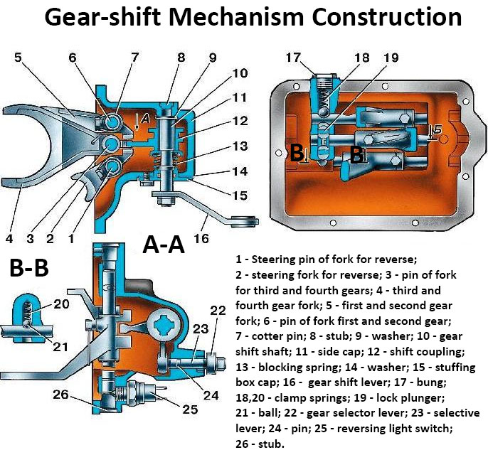
The exact installation of gears in the on and off positions provide clamps, consisting of balls and springs placed vertically in the tides of the gear housing. Balls are included in the grooves of the sliders. There are three indentations on each slider: one (middle) for the neural position and two for the corresponding gears. The distance between the grooves ensures the engagement of the gears along the entire length of the teeth.
The clamps provide exact installation of gears in the on and off positions. Clamps consist of balls 9 and springs 10. Balls enter in the grooves of the sliders. There are three grooves on each slider: one (middle) for the neutral position and two for the corresponding gears. The distance between the grooves ensures the engagement of the gears along the entire length of the teeth.
The gear-shift lock prevents accidental activation of two gears simultaneously. The gear-shift lock consists of a pin 11 and two pairs of balls 12. If the one of slider is moving — other two balls are locked. For locking balls on the sliders, there are corresponding grooves. If the average slide moves the balls come out of its recesses, enter to the recesses of the extreme sliders and lock them. If one of the side sliders moves, then the balls go out of its recesses and enter to the groove of the middle slide, while the other side crawl locks up due to the fact that the pin 11 moves to it side and press on the balls of with other side of the middle slide.
To set one of the sliders in motion, the other two must be placed in a neutral position. To engage the first gear or reverse gear, additional force must be applied to compress the spring of safety device 48 to the stop using a lever 51. Only then can the gearshift lever be moved to the position corresponding to the engagement of the first gear or reverse gear.
Gear-shift mechanism SUV
