The pushrod transfers the forces from camshaft to the valve.
It is made of steel or cast iron. The working surface of the pushrod is subjected to hardening and grinding to increase their durability.
The wearing will be less if push rods will be cast of iron and camshaft will be cast of steel. If the pushrod and the camshaft are steel, then bleached cast iron will be melted onto the push rod plate. Disk pushrods are widespread in engines with a lower valve arrangement.
An annular groove on the outer surface of the pushrod is necessary to lubricate the pusher-hole pair in the cylinder block. An adjusting bolt with a lock nut is screwed into the pushrod. In engines with an upper valve arrangement, cylindrical pushrods with one or two holes for oil drainage are used.
The working surface of the pushrod in contact with the camshaft cam is treated in a sphere.
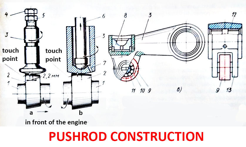
Pushrod construction:

a — disk pushrod with spherical bearing surface; b — cylindrical pushrod; c – lever push rod; 1 – camshaft; 2 – cam; 3 – pushrod; 4 – adjusting bolt; 5 – lock nut; 6 – connecting rod; 7 – oil drain hole; 8 – steel heel; 9 – roller; 10 – needle bearing; 11 – axis; 12 – sleeve; 13 – pushrod fork.
In a diesel engine, suspended lever pushers are used, freely mounted on a split axis located on four bearings above the camshaft. The axis 11 of the roller 9 rotates in needle bearings 10 mounted in the pushrod fork 13. The roller rolls over the camshaft cam. Therefore, sliding friction is replaced by rolling friction.
A steel heel 8 is pressed into the pusher from above with a matching surface, on which a hollow bar rests, transmitting movement to the rocker arm.