
Five speed gearbox construction
The front support of the drive shaft 1 is a ball bearing mounted in the recess of the crankshaft flange, the rear bearing is a ball bearing 2 located in the wall of the gearbox housing. The ball bearing 2 is closed with a lid and fixed with a retaining ring 3 and a nut. The driven shaft is supported by a ball bearing 17 and a roller bearing 37.
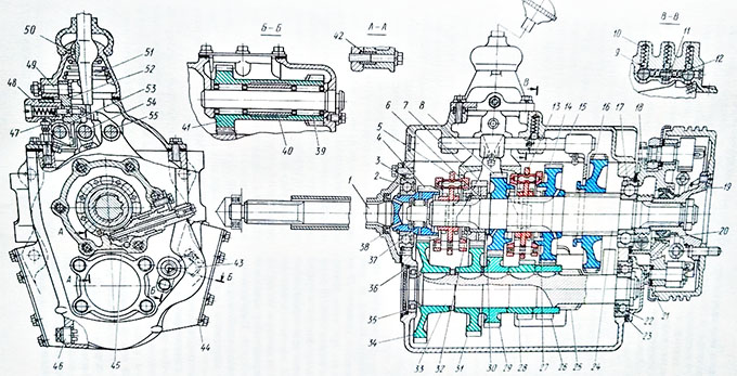
Five-speed gearbox construction scheme: 1 – drive shaft; 2, 17,22,35,37 and 39 – bearing; 3,21,23,36 – locking rings; 4 and 34 – permanent gearing gears of drive and intermediate shafts; 5 – synchronizer 4th and 5th gears; 6 – fourth gear bushing; 7 and 31 – gear wheels of 4th gear; 8 and 29 – gear wheels of 3rd gear; 9 – ball of clamp; 10 – clamp spring; 11 – gearshift lock pin; 12- ball of the lock; 13 – synchronizer 2nd and 4th gears; 14, 26 – gear wheels of 2nd gear; 15 – first gear shift and reverse gear fork; 16 – gear wheel of the first gear and reverse gear; 18 – parking brake bracket; 19 – universal joint flange; 2 and 38 – oil seals; 24 – driven shaft; 25 – drive gear wheel of the first gear; 27, 30 and 32 thrust washers; 28 – gear wheel reverse of intermediate shaft; 33 – intermediate shaft; 40 – spacer sleeve; 41 – gear wheels block of reverse; 42 – mounting sleeve; 43 – control plug; 44 – cap sunroof; 45 – speedometer drive gear; 46 – drain plug with a magnet; 47 – breather; 48 – first and reverse gear fuse; 49 – axis of intermediate lever; 50 – retainer; 51 – gear shift lever; 52 – intermediate lever; 53 –slider first gear shift and reverse gear; 54 – slider fourth gear shift and fifth gear; 55 – slider second gear shift and third gear.
At the rear end of this shaft are worn a speedometer drive worm and a splined hub with a cardan joint flange 19, secured with a nut and a washer. The ball bearing cover 17 also serves as a parking brake bracket.
The intermediate shaft 33 is supported by a ball bearing 22
and a roller bearing 35. The gear wheel 25 is made as one piece with the
intermediate shaft, and the gear wheels 26, 28, 29, 31 and 34 are mounted on
the shaft on the keys. The outer rings of ball bearings 17, 22 and roller
bearings 35 are fixed with retaining rings.
Gears wheels 4 and 34 connecting the drive and intermediate shafts, the wheels of the fourth, third, second gears have oblique teeth and are in constant gearing. Gears 7, 8, and 14 rotate freely on the driven shaft, on which there are also synchronizers 5 and 13, and there is a gear wheel 16 of the first gear and the reverse gear on the splines.
The first gear is engaged when the gear wheel 16 is moved forward until it engages with the wheel 25 on the intermediate shaft; At the same time, rotation through gears 15 and 16 is transmitted to the driven shaft. The second and third gears are included when the synchronizer 13 is moved back and forth respectively. To enable the fourth and fifth gears move back and forth the synchronizer 5. When the fifth gear is engaged, the driving and driven shafts are interconnected.
In the reverse gear enters a gear wheel 28 mounted on the intermediate shaft. When the gear wheel 16 moves backwards and engages with the small gear wheel of the block 41, the reverse gear is engaged.
In this case, the torque from the engine crankshaft through the gear wheels 4, 34, and 28, and the block 41, the gear wheel 16 is transmitted to the driven shaft, which will rotate in the opposite direction compared to the direction of its rotation when other gears are engaged. In the transmission case on both sides there are hatches with flanges for mounting the power take-off. The plug 43 closes the check-fill hole to fill and control the oil level.
Also you can learn four speed gearbox construction.